ZX Spectrum Raytracer
I love raytracers; in fact I’ve written half a book about them. Probably less known is my love for the ZX Spectrum, the 1982 home computer I grew up with, and which started my interest in graphics and programming. This machine is so ridiculously underpowered for today’s standards (and even for 1980s standards), the inevitable question is, to what extent could I port the Computer Graphics from Scratch raytracer to a ZX Spectrum?
The ZX Spectrum has a 3.5 MHz Z80 processor (1,000 times slower than current computers) that can’t multiply numbers (!!!), 48 KB of RAM (1,000,000 times smaller), and a 256x176 graphics mode (~200 times lower resolution) capable of displaying 15 colors (1,000,000 times fewer – and with some unusual quirks). This is an interesting setup for a CPU-intensive graphics application!
My plan was to implement this in Sinclair BASIC, the built-in programming language of the Spectrum. This is not just BASIC, but an ancient, very limited dialect of BASIC. For example, the only control structures are FOR and IF (and IF has no ELSE or even ENDIF); all variables are global; there are no function calls, only GO TO and GO SUB; etc. It’s also interpreted, so super slow. But at least it implements multiplications in software! Of course, I could rewrite the raytracer in assembler, but I thought it would be a fun challenge to see how much performance I could get out of BASIC, which is what I used as a child.
I set up a minimal environment: I write BASIC code using VS Code, compile it using BAS2TAP, and run it on the FUSE emulator. This gave me a pretty decent iteration speed.
As an aside, I hadn’t written BASIC in something like 30 years, and I was surprised at how quickly it all came back. I was between 4 and 10 when I was doing this, so I guess it sticks in the brain like anything you learn at that age, like languages and accents. Now let’s get coding like it’s 1984!
First iteration: a simple raytracer
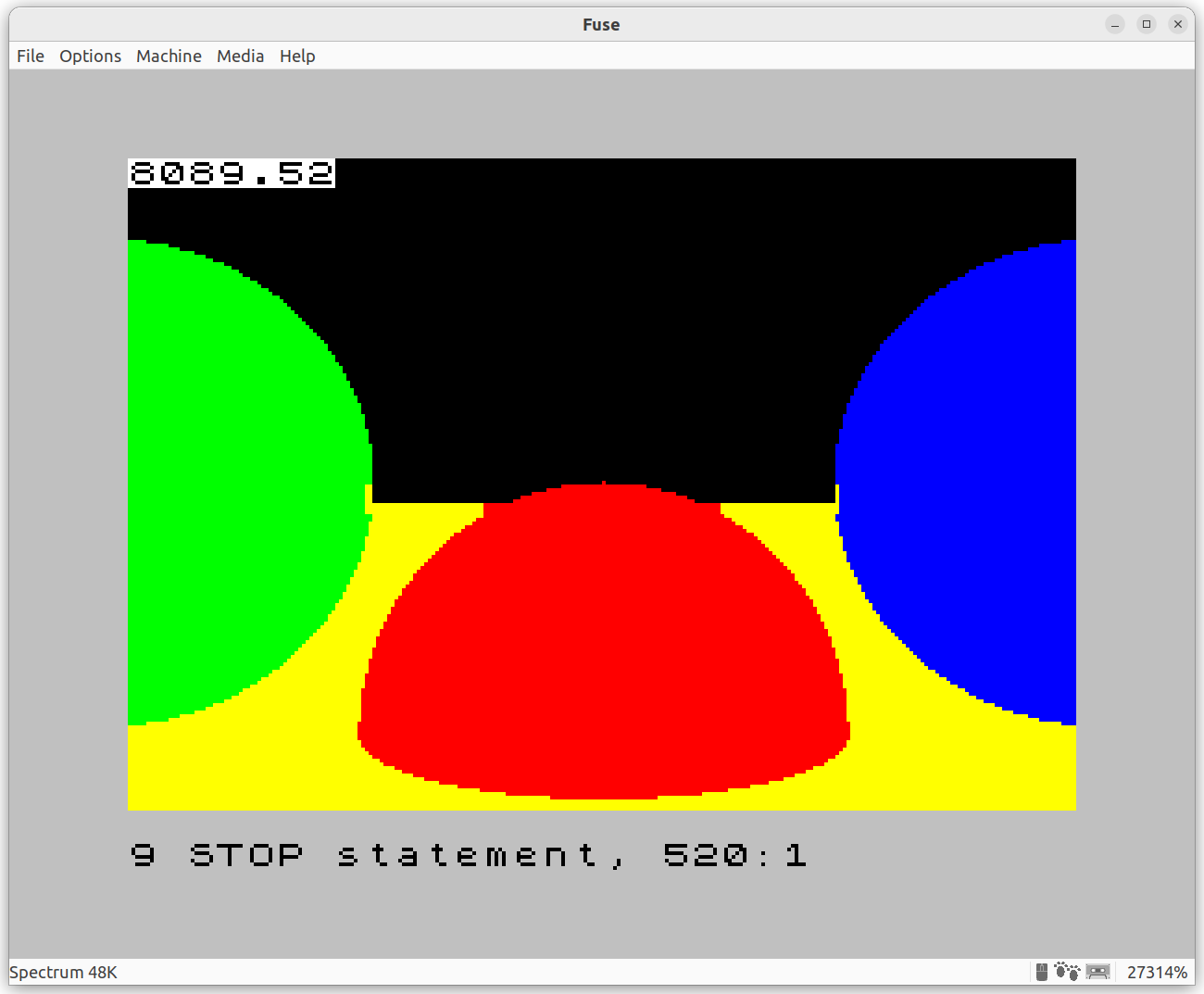
My first iteration was pretty straightforward: I ported the starter CGFS raytracing code to BASIC without much tweaking, outputting a 32x22-block image, and to my surprise, it worked well:
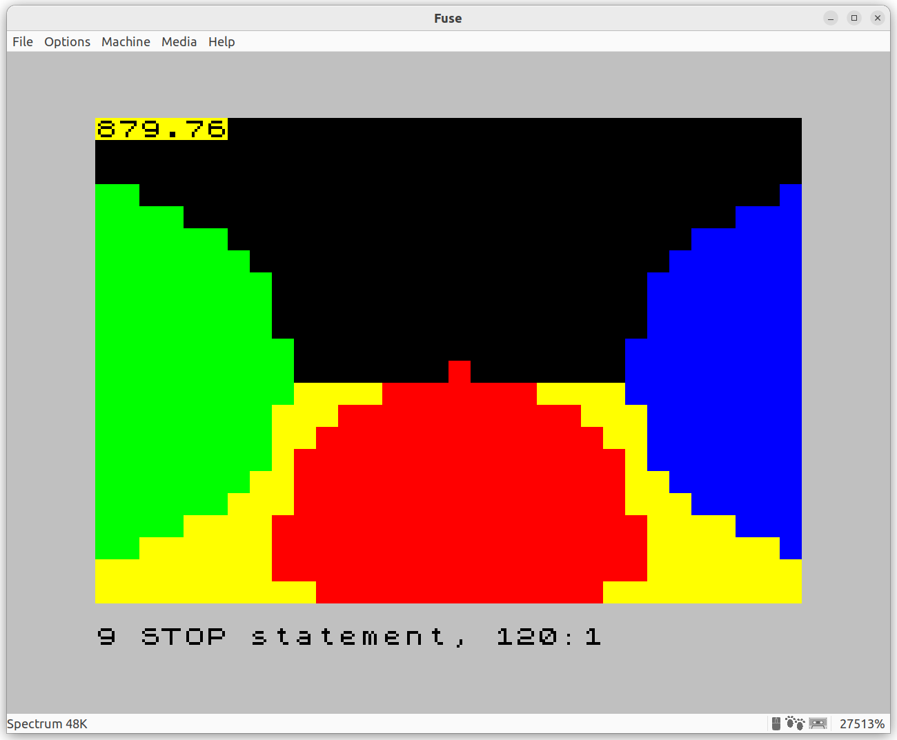
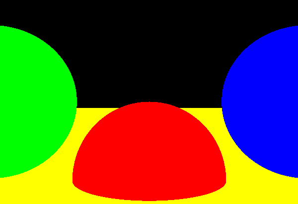
The number in the upper left corner, 879.76, is the time it took to render this image, in seconds. Yes, that’s almost 15 minutes. Here’s the same scene rendered by the CGFS raytracer in about a second, using the same scene and feature set:
The Spectrum version doesn’t look bad, considering the limitations! Let’s take a look at the code:
   1 BRIGHT 1: CLS

   5 LET ROX = 0
   6 LET ROY = 0
   7 LET ROZ = 0
   8 LET TMIN = 0
   9 LET TMAX = 10000

  10 FOR X = 0 TO 31
  20   FOR Y = 0 TO 21

  30     LET RDX = (X - 16) / 32
  31     LET RDY = (11 - Y) / 32
  32     LET RDZ = 1

  40     GO SUB 1000

  50     PAPER COL
  51     PRINT AT Y, X; " "

 100   NEXT Y
 105   GO SUB 3000: PRINT AT 0, 0; TIME
 110 NEXT X

 120 STOP


1000 REM ===== TraceRay =====
1001 REM Params: (ROX, ROY, ROZ): ray origin; (RDX, RDY, RDZ): ray direction; (TMIN, TMAX): wanted ranges of t
1002 REM Returns: COL: pixel color

1010 LET COL = -1: LET MINT = 0

1100 RESTORE 9000
1101 READ NS
1102 FOR S = 1 TO NS

1110    READ SCX, SCY, SCZ, SRAD, SCOL

1200    LET COX = ROX - SCX
1201    LET COY = ROY - SCY
1202    LET COZ = ROZ - SCZ

1210    LET EQA = RDX*RDX + RDY*RDY + RDZ*RDZ
1211    LET EQB = 2*(RDX*COX + RDY*COY + RDZ*COZ)
1212    LET EQC = (COX*COX + COY*COY + COZ*COZ) - SRAD*SRAD

1220    LET DISC = EQB*EQB - 4*EQA*EQC
1230    IF DISC < 0 THEN GO TO 1500

1240    LET T1 = (-EQB + SQR(DISC)) / 2*EQA
1241    LET T2 = (-EQB - SQR(DISC)) / 2*EQA

1250    IF T1 >= TMIN AND T1 <= TMAX AND (T1 < MINT OR COL = -1) THEN LET COL = SCOL: LET MINT = T1
1300    IF T2 >= TMIN AND T2 <= TMAX AND (T2 < MINT OR COL = -1) THEN LET COL = SCOL: LET MINT = T2

1500 NEXT S

1999 IF COL = -1 THEN LET COL = 0
2000 RETURN

3000 REM ===== Get timestamp in seconds =====
3001 LET TIME = (65536*PEEK 23674 + 256*PEEK 23673 + PEEK 23672) / 50
3002 RETURN

8998 REM ===== Sphere data =====
8999 REM Sphere count, followed by (SCX, SCY, SCZ, SRAD, COLOR)
9000 DATA 4
9001 DATA  0, -1, 4, 1, 2
9002 DATA  2,  0, 4, 1, 1
9003 DATA -2,  0, 4, 1, 4
9004 DATA 0, -5001, 0, 5000, 6
The structure of the code should look familiar if you’re familiar with raytracers in general, and with the CGFS raytracer in particular, despite being written in an ancient dialect of BASIC. I’ll still walk through the code to point out the quirks of the Spectrum.
First, line numbers. Every line had to have a number, so you could use GO TO or GO SUB. Lines supported multiple statements separated by a colon – especially useful for the IF ... THEN statement, considering there’s no END IF!
You’ll notice the line numbers are all over the place. The Spectrum BASIC editor was line-oriented, so while it was possible to change line numbers, it was very time-consuming. So you’d number your lines in multiples of 10, so you had “space” to add lines in between if needed.
We start with this:
1 BRIGHT 1: CLS
The Spectrum has a pretty quirky graphics mode. I’ll get into the details in the next section. For now, let’s just say that BRIGHT 1 chooses the bright version of the color palette, and CLS clears the screen. So we’re ready to start drawing something.
Then comes the main loop of the rayrtacer:
  5 LET ROX = 0
  6 LET ROY = 0
  7 LET ROZ = 0
  8 LET TMIN = 0
  9 LET TMAX = 10000

 10 FOR X = 0 TO 31
 20   FOR Y = 0 TO 21

 30     LET RDX = (X - 16) / 32
 31     LET RDY = (11 - Y) / 32
 32     LET RDZ = 1

 40     GO SUB 1000

 50     PAPER COL
 51     PRINT AT Y, X; " "

100   NEXT Y
105   GO SUB 3000: PRINT AT 0, 0; TIME
110 NEXT X

120 STOP
Lines 5 to 9 set some of the parameters that are constant throughout the main loop. BASIC had arrays but they were pretty inconvenient to use, so using them to represent points and vectors was a non-starter. So the ray origin RO is represented by the three variables ROX, ROY and ROZ.
Lines 10 to 110 form the main loop, iterating over the canvas (32x22 squares). After each pass of the inner loop, rendering a column of squares, line 105 does the equivalent of a function call: GO SUB 3000 transfers control flow to the subroutine at line 3000:
3000 REM ===== Get timestamp in seconds =====
3001 LET TIME = (65536*PEEK 23674 + 256*PEEK 23673 + PEEK 23672) / 50
3002 RETURN
Line 3000 starts with REM, short for “remark”. We call them “comments” these days, but the ZX Spectrum is British, the brainchild of mad genius Sir Clive Sinclair. So this line is just a comment.
The magical incantation in line 3001 reads the current timestamp in seconds. How? PEEK takes a memory address and returns its contents. All this line does is read a 24-bit number stored in memory, representing the internal FRAME counter; this counter is incremented every 20ms, so we divide it by 50 to convert it to seconds, and store it in the variable TIME.
Every variable in the program is global, so RETURN in line 3002 just returns flow control to the caller, and the “return value” of the function is implicitly the TIME global variable. This GO SUB / RETURN mechanism is very similar to CALL / RET in assembly.
Finally, line 120 terminates the program.
Now let’s take a look at the inner loop. Lines 30 to 32 convert canvas coordinates to viewport coordinates (CanvasToViewport in CGFS). The ray direction is represented by (RDX, RDY, RDZ).
Line 40 does another “function call”, this time to the equivalent of TraceRay. When it returns, the variable COL will contain the color of whatever the ray hit.
Lines 50 and 51 finally draw the block. This is done by setting the PAPER (background) color and drawing a space (more on this later).
Now let’s take a look at TraceRay starting at line 1000. It starts with a comment block documenting the implicit inputs and outputs:
1000 REM ===== TraceRay =====
1001 REM Params: (ROX, ROY, ROZ): ray origin; (RDX, RDY, RDZ): ray direction; (TMIN, TMAX): wanted ranges of t
1002 REM Returns: COL: pixel color
Because there are no function arguments or return values, everything is global, implicit, and by convention. In this case, the inputs are (ROX, ROY, ROZ), (RDX, RDY, RDZ), TMIN and TMAX, and the return value is in the variable COL. This represents an index into the fixed color palette of the ZX Spectrum.
Line 1010 initializes the values we need to keep track of the closest intersection found so far, and the color of the sphere at the intersection:
1010 LET COL = -1: LET MINT = 0
Then we start the “for each sphere” loop:
1100 RESTORE 9000
1101 READ NS
1102 FOR S = 1 TO NS
1110    READ SCX, SCY, SCZ, SRAD, SCOL
Line 1100 resets a “data pointer” to line 9000, which contains the scene data:
8998 REM ===== Sphere data =====
8999 REM Sphere count, followed by (SCX, SCY, SCZ, SRAD, COLOR)
9000 DATA 4
9001 DATA  0, -1, 4, 1, 2
9002 DATA  2,  0, 4, 1, 1
9003 DATA -2,  0, 4, 1, 4
9004 DATA  0, -5001, 0, 5000, 6
The READ statement in line 1101 reads the first value (the number 4 in line 9000) into the variable NS. Then line 1102 starts the “for each sphere” loop, and the first thing we do in line 1110 is read the 5 values defining a sphere into variables. After that first batch of READ statemends the data pointer is now at the first value of line 9002, ready to be read during the next iteration of the loop.
Lines 1200 to 1300 solve a straightforward ray-sphere intersection equation, with lines 1250 and 1300 keeping track of the closest intersection:
1200    LET COX = ROX - SCX
1201    LET COY = ROY - SCY
1202    LET COZ = ROZ - SCZ

1210    LET EQA = RDX*RDX + RDY*RDY + RDZ*RDZ
1211    LET EQB = 2*(RDX*COX + RDY*COY + RDZ*COZ)
1212    LET EQC = (COX*COX + COY*COY + COZ*COZ) - SRAD*SRAD

1220    LET DISC = EQB*EQB - 4*EQA*EQC
1230    IF DISC < 0 THEN GO TO 1500

1240    LET T1 = (-EQB + SQR(DISC)) / 2*EQA
1241    LET T2 = (-EQB - SQR(DISC)) / 2*EQA

1250    IF T1 >= TMIN AND T1 <= TMAX AND (T1 < MINT OR COL = -1) THEN LET COL = SCOL: LET MINT = T1
1300    IF T2 >= TMIN AND T2 <= TMAX AND (T2 < MINT OR COL = -1) THEN LET COL = SCOL: LET MINT = T2
We finish the loop checking if there were no intersections, in which case we set the color to 0 (black), and return:
1999 IF COL = -1 THEN LET COL = 0
2000 RETURN
And that’s all there is to it. We get our super slow, super low-res output:
I still find it pretty impressive that this only takes 50 lines of relatively straightforward code in an underpowered early 80s machine!
But this is just a start. Why stick to 32x22 when the usable pixel dimensions of the screen are 256x176?
Second iteration: higher resolution, and handling attribute clashes
You might think that increasing the resolution of this raytracer is as simple as changing the outer loop to 256x176 instead of 32x22 and drawing individual pixels using PLOT instead of chunky squares using PRINT. This would be 64 times slower (16 hours instead of 15 minutes) but it would work – except in the quirky graphics mode of the ZX Spectrum!
The first version of the ZX Spectrum had a grand total of 16 KB of RAM, so memory efficiency was absolutely critical (I had the considerably more luxurious 48 KB model). To help save memory, video RAM was split in two blocks: a bitmap block, using one bit per pixel, and an attributes block, using one byte per 8x8 block of pixels. The attributes block would assign two colors to that block, called INK (foreground) and PAPER (background).
So you could use PLOT to set or clear the bit corresponding to a pixel, which would then take one of the two colors assigned to that block. This means each 8x8-pixel block can show one or two different colors, but never three or more.
This all worked great for text-based applications, since characters were also 8x8 blocks, but for anything graphic, especially games, it was super limiting. This limitation gives Spectrum games its very characteristic aesthetic, because artists had to work around this, usually by designing screens and sprites aligned to a 8x8 pixel grid, or going full monochrome, or accepting that attribute clash was a fact of life.
Back to the raytracer. Increasing the resolution is easy. Dealing with attribute clash, not so much.
There’s no perfect solution: no matter what I do, each 8x8 block can show up to two colors. So what I did was implement an approximation algorithm. I collect the colors present in the 8x8 block, find the most common and second most common, and draw every pixel using one of the two.
The outer loop changes a bit to reflect the higher resolution and the processing on 8x8-block chunks:
 10 FOR X = 0 TO 255 STEP 8
 20   FOR Y = 0 TO 175 STEP 8

...

500   NEXT Y
505   GO SUB 3000: PRINT AT 0, 0; TIME
510 NEXT X
520 STOP
Then we trace the 64 rays, collecting the colors in an array:
 30      DIM C(64)
 31      LET CI = 1
 32      DIM A(8)

120     REM --- For each 8x8 block, collect the pixel colors and their counts ---
125     FOR U = X TO X+7
126       FOR V = Y TO Y+7

130         LET RDX = (U - 128) / 256
131         LET RDY = (V - 88) / 256
132         LET RDZ = 1

140         GO SUB 1000
141         LET C(CI) = COL
142         LET CI = CI + 1
143         LET A(COL+1) = A(COL+1) + 1

160       NEXT V
161     NEXT U
Line 30 DIMensions the variable C as a 64-element array. Array indexes start at 1, so line 31 initializes CI (C-index) to 1. Line 32 creates another array A which will hold the color counts.
Lines 140 to 143 call TraceRay and store the results: the pixel color in C, and the updated color count in A. Colors go from 0 to 7 but indexes go from 1 to 8, so we need to use COL+1 as the index.
Next we need to find the most and second-most frequent colors:
199     REM --- Find the most and second most frequent colors in this 8x8 block ---
201     LET MFC = 0
202     FOR C = 1 TO 8
203       IF A(C) > MFC THEN LET MFC = A(C): LET MFI = C
204     NEXT C
205     LET FCOL = MFI - 1

207     LET II = MFI: LET MFC = 0: LET MFI = 0
208     FOR C = 1 TO 8
209       IF C <> II AND A(C) > MFC THEN LET MFC = A(C): LET MFI = C
210     NEXT C
211     LET SCOL = MFI - 1
Time to draw some pixels. If all the pixels are the same color, just paint the block:
259     REM --- If there's only one color, paint the whole block --
260     IF SCOL <> -1 THEN GO TO 300
270     POKE 22528 + X/8 + 32*(21-Y/8), 64 + FCOL * 8
280     GO TO 500
That POKE requires an explanation. POKE puts a byte in a memory address. The first parameter is the address of this 8x8 block in the attributes block. The second parameter, the byte representing the INK and PAPER values, is the combination of the INK color shifted left 3 bits, plus a bit to turn on the BRIGHT attribute.
If not all pixels are the same color, we need to plot them individually. The PAPER color of the block is set to the most frequent color (so there’s fewer pixels to plot), we go over the array, and any pixel that isn’t the most frequent color is drawn with INK color set to the second most frequent color:
300     REM --- Otherwise set the PAPER to the most frequent color, and draw everything else in the second most frequent color --
301     LET CI = 1
310     FOR U = X TO X+7
311       FOR V = Y TO Y+7

320         IF C(CI) <> FCOL THEN PLOT INK SCOL; PAPER FCOL; U, V
321         LET CI = CI + 1

350       NEXT V
351     NEXT U
This works pretty well!
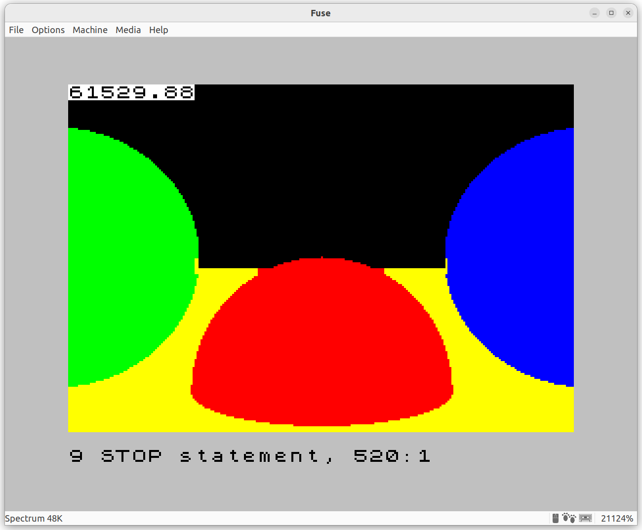
Attribute clash still happens. Look at this magnified part:
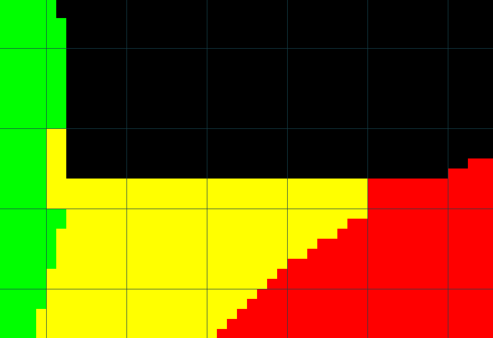
With a grid overlaid to show block boundaries, the problem is easier to see. The two blocks that look “wrong” should have three colors: black, yellow, and either green or red. But the Spectrum can’t do that, so this is what the algorithm above ends up doing.
You can take a look at the full source code for this iteration.
The next thing to notice is that it’s just ridiculously slow - over 17 hours! Even on the emulator hitting 20,000% speed, it takes a while to render. Can we do better?
Third iteration: performance improvements
I went for an optimization pass. Here’s what I did:
For each 8x8 block, trace rays for the 4 corners, and if the color is the same in all, paint the whole block. Most of the time this does 4 rays per block instead of 64, so by itself it speeds up rendering by 16x. Of course if there were small objects that fell fully inside a block, the raytracer would miss them; but for this test scene, it feels like it’s a fair approximation.
Avoid multiplications and divisions at all costs. The Z80 can’t do multiplication in hardware (let alone division), so BASIC implements it in software, and it’s slow.
Hardcode some constants based on assumptions. Notably, the ray origin is always (0, 0, 0),
t_minis always 0, andt_maxis always+inf, so that saves some computation.Precompute values when possible. Why store the sphere radius as data and square it, when it can be stored squared to begin with?
Move computed values to outer loops when possible. For example, values related to X are constant for every Y, and can be computed fewer times.
Inlined the “most frequent color” subroutine, and specialized the first case to not ignore any color.
Tweaked the line numbers to make sure
GO SUBdidn’t land on aREMline; believe it or not, processing a line that contains a comment takes time!Used shorter variable names. This BASIC is interpreted, so every time you reference a variable, it’s looked up by name…
I also tried some optimizations that didn’t work, like reading the
DATAinto an array first, or putting certain expressions into variables. I have the vague feeling that the order in which variables are defined is important – I need to read more about this.There’s some optimizations that help marginally, but hinder readability, so I chose not to implement them.
All in all, the result is pretty good. The image is pixel-identical, but the runtime is down to 2 hours and a bit:
You can take a look at the full source code for this iteration.
Fourth iteration: light (just the one)
Initially I had stopped myself here; given the limitations of the environment, I felt like there wasn’t much more that could be done.
The obvious next step is to implement lighting. The lighting equations and algorithms are relatively straightforward, but the main problem is the very limited set of colors the ZX Spectrum can represent. To recap, it’s a fixed set of 7 colors, in normal and bright versions, plus black:

Even if I had the light intensity value at every pixel, I can’t just multiply it by the sphere color to get the shaded color, like I can do trivially in RGB. What to do?
Tradeoffs, that’s what. I can simulate shades of a color by alternating the color and black in the right amounts. I can do this on a 8x8 block basis, setting the INK to the color, PAPER to black. The tradeoff is that there will be attribute clashing.
How to decide whether to plot a pixel or leave it black? My first idea was to use the light intensity, a real number between 0.0 and 1.0, as the probability that a pixel would be plotted with the color (and left black otherwise). This worked, but it looked ugly. There’s something better, called ordered dithering. The idea is to have a matrix of thresholds, one per pixel, that helps determine whether to plot the pixel. The thresholds are arranged in such a way that they produce repeatable, pleasing patterns of pixels for any intensity level. There’s a 8x8 dithering matrix, which fits perfectly the 8x8 color blocks I’m processing, so it was surprisingly easy to implement.
For the sake of simplicity, I decided to have just one directional light. Even with ordered dithering, there are not enough shades I can display that will adequately represent the nuances of multiple lights illuminating the same object. For the same reason, I went for diffuse lighting only, no specular component.
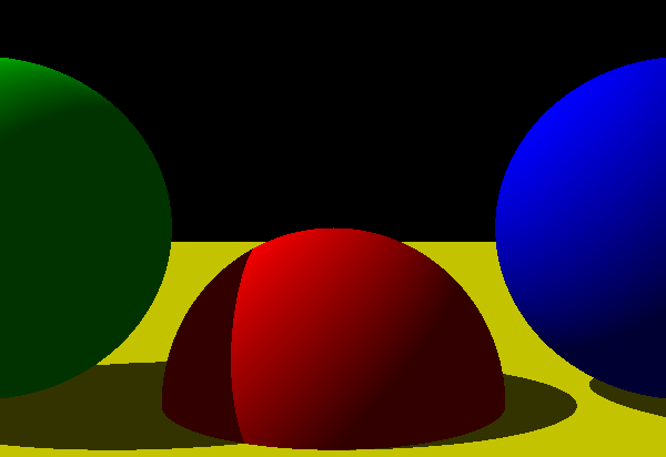
So the goal was to render something like this:
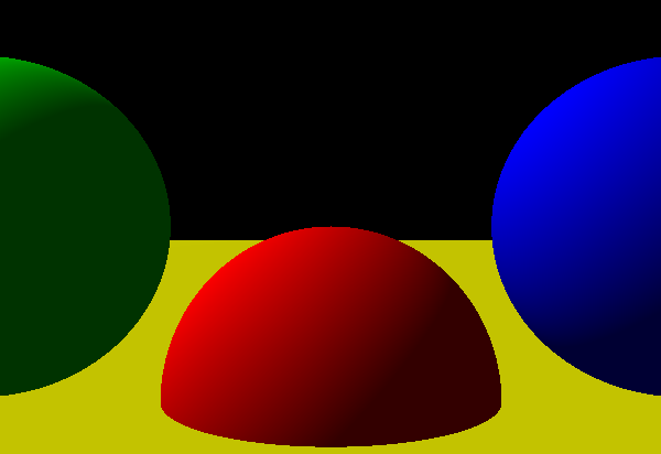
How close could I get to that on a humble ZX Spectrum?
Here are the relevant changes I made to the code:
I could no longer use the 4-rays-per-8x8-block trick, because the light intensity at each pixel could be different. Could have computed one intensity per block, but I didn’t want to lose light resolution. So performance took a big hit compared to the previous iteration. The exception is if the 4 corners of the 8x8 block are black, in which case I can safely ignore it.
The lighting part is pretty simple: in the TraceRay subroutine, I needed to keep track of the index of the closest sphere (so I also had to load the sphere data into an array S at the start of the program). After the sphere loop, if the ray hits any sphere, I compute the intersection between the ray and the sphere, the normal at that point in the sphere, and finally the illumination at that point:
1601 LET NX = DX*MT - S(CS, 1): LET NY = DY*MT - S(CS, 2): LET NZ = DZ*MT - S(CS, 3)
1610 LET PL = AI
1615 LET NL = (NX*LX + NY*LY + NZ*LZ)
1620 IF NL > 0 THEN LET PL = PL + DI * NL / SQR(NX*NX + NY*NY + NZ*NZ)
In that fragment, CS is the index of the Closest Sphere; PL is a new output variable representing Pixel Lighting; (LX, LY, LZ), DI and AI are set elsewhere, and represent the direction of the light, its intensity, and the intensity of the ambient light, respectively. For performance reasons, LX, LY, LZ represent a normalized vector, so I can skip an additional SQR and division in line 1620.
I don’t need to find the second most frequent color in each 8x8 block anymore, because each block will only display the most frequent color and black.
I added some code to load the Bayer ordered dither matrix into an array:
   3 GO SUB 7000

   ...

6999 REM ===== Initialize 8x8 Bayer matrix =====
7000 DIM H(64)
7001 RESTORE 7100
7002 FOR I = 1 TO 64
7003   READ H(I): LET H(I) = H(I) / 64
7004 NEXT I
7005 RETURN

7100 DATA  0, 32,  8, 40,  2, 34, 10, 42
7101 DATA 48, 16, 56, 24, 50, 18, 58, 26
7102 DATA 12, 44,  4, 36, 14, 46,  6, 38
7103 DATA 60, 28, 52, 20, 62, 30, 54, 22
7104 DATA  3, 35, 11, 43,  1, 33,  9, 41
7105 DATA 51, 19, 59, 27, 49, 17, 57, 25
7106 DATA 15, 47,  7, 39, 13, 45,  5, 37
7107 DATA 63, 31, 55, 23, 61, 29, 53, 21
And finally, before plotting a pixel, I compare its light intensity with the corresponding threshold in the Bayer matrix:
320 IF C(CI) > 0 AND H(CI) <= L(CI) THEN PLOT U, V
I ran this iteration, and honestly, I stared at it in disbelief for a good minute:
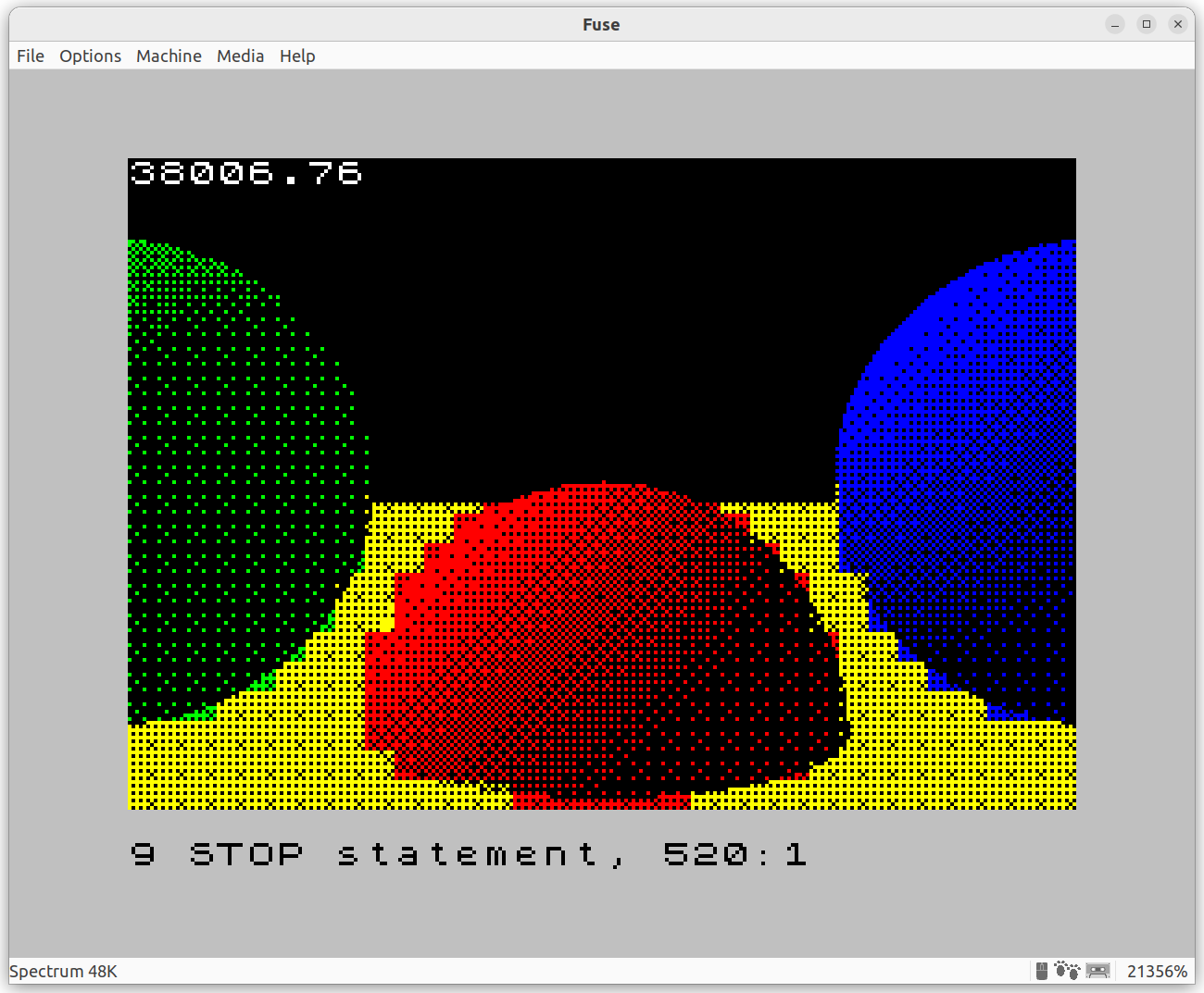
First of all, it works!
It’s pretty slow compared to the previous iteration, mostly because the missing 4-rays-per-block trick, plus the additional lighting calculations. But it’s not that bad.
Attribute clashing is still there, and it’s a lot more obvious now. Could this be improved? Maybe. The yellow/red clashes look like could be improved by making the blocks red and yellow, and forgoing the shading detail (because there would be no black). For green/yellow and blue/yellow, looks like black/yellow, blue/yellow and again black/yellow would make it look better. Hmmmm. Maybe I’ll get back to this.
You can take a look at the full source code for this iteration.
Fifth iteration: shadows
At this point I’m feeling pretty comfortable with the environment, I’m coding like it’s 1984, so I want to see how far I can take this. Next step: shadows.
Most of the pieces are already in place. The theory is relatively simple: before computing lighting for a point, need to figure out whether there’s an object between the point and the light, blocking it (i.e. casting a shadow). I just had to implement a specialized version of TraceRay that traces from the intersection of the primary ray and a sphere, in the direction of the directional light, and returns as soon as it finds any intersection:
2090 REM ----- Specialized TraceRay for shadow checks -----
2091 REM Params: (IX, IY, IZ): ray start; (LX, LY, LZ): ray direction (directional light vector)
2092 REM Returns: H = 1 if the ray intersects any sphere, H = 0 otherwise
2093 REM Optimizations: (TMIN, TMAX) hardcoded to (epsilon, +inf)

2100 LET A = 2*(LX*LX + LY*LY + LZ*LZ)

2110 FOR S = 1 TO NS

2111    LET CX = IX - S(S,1): LET CY = IY - S(S,2): LET CZ = IZ - S(S,3)
2120    LET B = -2*(CX*LX + CY*LY + CZ*LZ)
2130    LET C = (CX*CX + CY*CY + CZ*CZ) - S(S, 4)

2140    LET D = B*B - 2*A*C
2150    IF D < 0 THEN GO TO 2210
2160    LET D = SQR(D)

2170    LET T = (B + D) / A
2180    IF T > 0.01 THEN LET H = 1: RETURN
2190    LET T = (B - D) / A
2200    IF T > 0.01 THEN LET H = 1: RETURN

2210 NEXT S
2220 LET H = 0: RETURN
This is called right before computing illumination:
1600 LET IX = DX*MT: LET IY = DY*MT: LET IZ = DZ*MT
1601 LET NX = IX - S(CS, 1): LET NY = IY - S(CS, 2): LET NZ = IZ - S(CS, 3)
1610 LET PL = AI

1612 GO SUB 2100: IF H = 1 THEN RETURN

1615 LET NL = (NX*LX + NY*LY + NZ*LZ)
1620 IF NL > 0 THEN LET PL = PL + DI * NL / SQR(NX*NX + NY*NY + NZ*NZ)
And here’s what comes out…
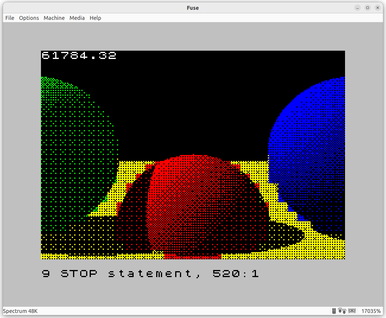
Compare with the output of the CGFS raytracer:
Pretty slow due to the extra computation (back to 17 hours), but definitely worth it!
You can take a look at the full source code for this iteration.
What next?
The obvious next step would be to implement reflections. But it would be practically impossible to blend colors together in a meaningful way. So objects would be either fully reflective or not reflective at all, and it would just look weird. Recursion would be an interesting problem: the Spectsum supports it, but because there are no local variables, each recursive call would overwrite the global variables, so I’d have to manage my own stack. Doable, but doesn’t sound worth the effort.
Another axis is performance. I could rewrite the whole thing in assembly and see how fast can I make it go. I could control how much precision I need, so maybe fixed-point math would do it (or a less precise version of SQR). Maybe some other time!
Finally, the attribute clash at object boundaries still bothers me. I have a couple of ideas that might improve the situation, although the limitations of the Spectrum are such that it will never be 100% fixed.
Nostalgic rant
This was a fun weekend project. Entirely pointless, but fun!
It was nice to write Sinclair BASIC after 30 years. Even though the language is the same, I’m not – I found myself thinking higher-level concepts and then translating them to BASIC. I don’t know whether this is because modern languages give me a better vocabulary to think in, that I can then translate to BASIC, or because I’m not 10 anymore. Could be both.
Specifically, this program makes judicious use of GO TO, which as everyone knows, it’s Considered Harmful™. Back in the day it was pretty much all we had: no function calls, only subroutines using GO SUB; no WHILE or REPEAT; IF doesn’t have END IF; FOR doesn’t have BREAK or CONTINUE (the keywords exist, but they don’t do what you think they do). So using GO TO is unavoidable. And sure, it can lead to spaghetti code, but it doesn’t have to; my own code here, although admittedly simple, is structured cleanly.
I also missed the immediacy and the simplicity of the environment. No frameworks, no dependencies, barely any abstractions (even multiplication is implemented in software!). The ZX Spectrum was fully knowable. The whole Z80 instruction set, the quirks of the ROM and the ALU, everything fits in your head pretty easily. You could reason about peformance down to the processor cycle level – no caches or pipelines or anything else to make your life difficult. I miss all that. Kids These Days™ will never get to experience an environment like this, and that makes me sad.
9999 STOP